Plastic part design is a critical step in the injection molding process that directly impacts product quality, manufacturing efficiency, and cost.
Understanding key design principles helps engineers create parts that are both functional and easy to produce. This guide introduces essential guidelines to optimize plastic part design for successful plastic injection molding.
Material Selection Criteria Of Plastic Parts Design
Material selection is critical to the development process and overall success of plastic part design. When choosing the appropriate plastic resin, considerations include mechanical properties, chemical resistance, heat resistance, dimensional stability, and compatibility with manufacturing processes.
Different plastic materials exhibit varying shrinkage rates during cooling, which can affect dimensional accuracy and part quality.
For example, semi-crystalline materials like polypropylene (PP) and polyamide (PA) have higher and more anisotropic shrinkage compared to amorphous materials such as ABS and polycarbonate (PC).
Material also influences surface finish and tolerances. Heat resistance requirements may lead to the selection of engineering plastics or reinforced resins, impacting mold construction and cost.
Designers should collaborate closely with mold makers to ensure material performance aligns with part function and manufacturing needs.
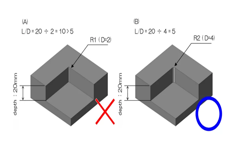
Additionally, material choice relates to core pin and blind hole design, where blind hole depth-to-diameter ratios must be controlled to prevent deformation and defects. Weld line locations should also be considered in design to avoid compromising strength and appearance.
Determining the material early in the design process helps follow key design guidelines, optimize part geometry, reduce molding defects, and achieve efficient manufacturing with appropriate wall thickness and draft angles, ensuring consistency and quality of the final product.
Material Type | Examples | Shrinkage Rate | Warpage Risk |
|---|---|---|---|
Amorphous materials | ABS, PC, PMMA | 0.4–0.7% | Lower (isotropic) |
Semi crystalline materials | PP, POM, PA6/PA66 | 1.2–2.0% | Higher (anisotropic) |
Wall Thickness Of Molded Parts Design
Wall thickness is a fundamental aspect of plastic part design that greatly influences manufacturability, part quality, and production efficiency. Maintaining consistent wall thickness throughout the part is crucial to avoid common defects such as sink marks, warpage, voids, and internal stresses.
Non-uniform wall sections cool at different rates, causing differential shrinkage that can lead to dimensional inaccuracies and surface defects.
Proper wall thickness depends on the selected material and the part’s functional requirements. For example, thin walls are preferred for faster cooling and reduced cycle times, but excessively thin areas may cause incomplete filling or weak structural integrity.
Conversely, overly thick sections increase material costs, prolong cooling times, and raise the risk of surface defects like sink marks and voids.
To optimize wall thickness, designers should aim for gradual transitions between different thicknesses rather than abrupt changes. Variations in wall thickness should not exceed 10% to maintain consistent cooling and minimize molding defects.
Uniform wall thickness also simplifies mold design and enhances production efficiency by enabling faster cycle times and reducing scrap rates.
Incorporating uniform wall thickness principles during injection molding design helps avoid surface defects and improves the overall quality and consistency of the molded parts.
Additionally, considering the nearest side wall when creating thin areas ensures proper material flow and reduces the likelihood of defects.
By carefully balancing proper injection molding wall thickness with the part’s mechanical and aesthetic requirements, designers can create plastic components that are both functional and cost-effective to manufacture.
Material | Typical Wall Range | Notes |
|---|---|---|
ABS | 1.0–3.0 mm | Consumer electronics, automotive trim |
PP | 1.5–4.0 mm | Containers, packaging |
PC (optical) | 0.8–1.5 mm | Lenses requiring clarity |
Glass-filled nylon | 1.5–3.5 mm | Structural components |
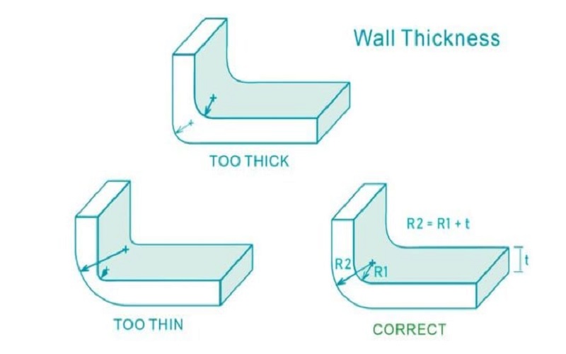
Corner Radii and Fillets
Sharp corners cause stress concentration factors of 3–5× in 90° turns, slowing material flow and raising tool costs 20–50% due to the need for electrical discharge machining. Rounded corners enable conventional CNC machining and dramatically improve fatigue life.
Rules of Thumb for Radii
Minimum inside radius: approximately 0.5× nominal wall thickness (e.g., 0.75 mm on a 1.5 mm wall)
External radius: internal radius + wall thickness (e.g., 2.25 mm external for 0.75 mm internal on 1.5 mm wall)
Minimum radius for glass-filled polymers: ≥0.75× wall thickness to prevent fiber breakage
Practical Example
A snap feature with 0.25 mm external radius cracked at 5,000 cycles during testing. Increasing that radius to 1.0 mm on the same 2 mm wall allowed the feature to sustain 20,000+ cycles.
The larger radius reduces stress concentration, improves plastic flow during filling, and diffuses load across more material.
Draft Angles Design For Injection Molded Parts
Draft is the progressive taper along the mold opening direction. Proper draft angle for injection molding design reduces ejection force by 30–50% by compensating for the 0.5–2% shrinkage that pulls molded parts onto cores.
Concrete Angle Ranges
Surface Type | Minimum Draft |
|---|---|
Highly polished | 0.5° |
Standard vertical walls | 1–2° |
Light texture | 2–3° |
Heavy grain/Class-A automotive | 3–5° |
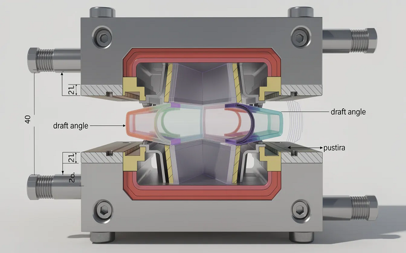
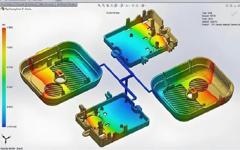
In the image below, the mold opening adopts a tapered wall design, and the vertical surfaces have appropriate draft angles.
This design minimizes defects during the injection molding process and ensures the structural integrity of the molded part.
Ribs, Bosses, and Structural Features In Injection Molding Design
Ribs and bosses are essential structural elements in plastic part design that enhance strength and functionality without significantly increasing wall thickness or material usage. Understanding their design principles is critical to avoid common molding defects and ensure manufacturability.
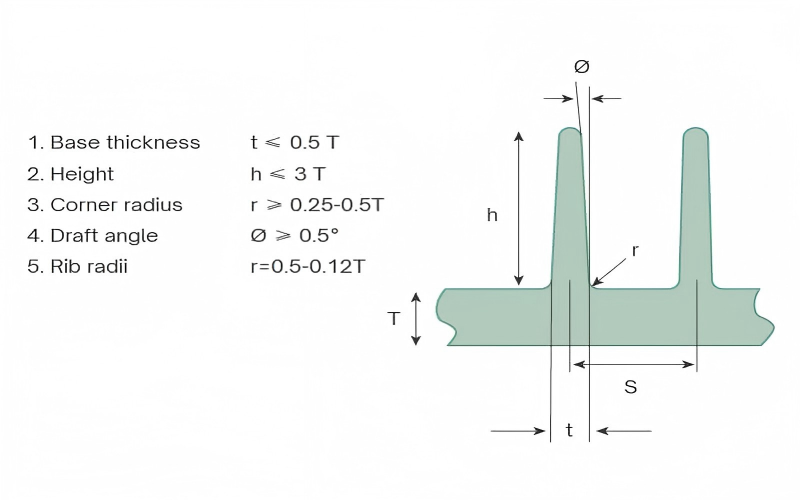
Rib Design
Ribs are vertical features that enhance the structural integrity and load-bearing capacity of plastic parts without significantly increasing wall thickness.
They help increase rigidity and prevent part deformation under mechanical stress. However, ribs must be designed with care to avoid issues such as sink marks, short shots, and ejection difficulties.
A key guideline is that rib thickness should not exceed 60% of the nominal wall thickness to avoid sink marks caused by differential shrinkage.
Excessively thick ribs create thick sections that cool slower than adjacent walls, leading to cosmetic defects and dimensional inconsistencies. Additionally, rib height should generally be limited to less than three times the nominal wall thickness to avoid molding problems and ejection challenges.
Using multiple smaller ribs instead of one large rib can distribute stresses more evenly and improve mold filling. Generously rounding rib corners and bases also facilitates molten plastic flow and reduces stress concentrations, which improves ribs design and part strength and reduces the risk of cracking.
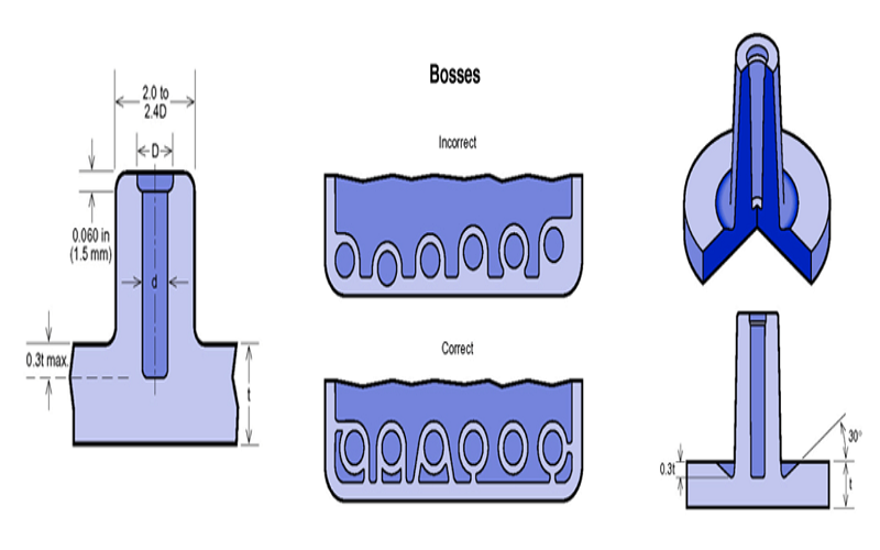
Boss Design
A boss feature finds use in many plastic part designs as a point of attachment and assembly.Proper boss design is critical to ensure structural integrity and ease of assembly.
Boss height should be less than three times the outer diameter to avoid creating thick sections that cause sink marks and warpage.
The thickness of the boss wall should be consistent with the nominal wall thickness to maintain uniform cooling and shrinkage. Incorporating fillets at the base of bosses reduces stress concentrations and improves material flow during injection molding.
When bosses are designed to accept threaded inserts or self tapping screws, proper engagement length and boss height must be ensured to provide sufficient strength and prevent cracking during assembly. Using rib support around bosses can further enhance their load-bearing capability.
Integration and Manufacturing Considerations
Both ribs and bosses affect mold complexity and part ejection. Deep or tall ribs may require additional draft angles or supporting ribs to simplify mold construction and facilitate ejection. Avoiding undercuts in these features helps reduce mold complexity and cost.
Careful attention to rib thickness, height, and placement, as well as boss dimensions and support, enables plastic components to be manufactured efficiently with minimal defects.
These structural features, when designed according to best practices, contribute significantly to the functional performance and durability of injection molded parts.
DFM Considerations and Pitfall Prevention
In the process of plastic part design, reasonable design principles not only affect the quality and performance of the product but also directly impact manufacturing efficiency and cost control.
Mastering key design points helps avoid common defects and achieve efficient and economical injection molding production.
The following content will detail important guidelines in plastic part design to assist engineers in optimizing their design schemes.
Parting Line and Gate Location Design Principles
The parting line is the interface where the two halves of the injection mold separate. During design, the parting line should be positioned to avoid critical aesthetic areas of the product as much as possible, reducing visible seams and subsequent finishing work.
Proper arrangement of the parting line helps simplify mold structure, lower manufacturing costs, and improve product appearance quality.
The gate location determines the entry point of molten plastic into the mold cavity. Correct gate design ensures uniform plastic flow, prevents air traps and weld lines, and reduces stress concentration and deformation.
Weld Lines, Air Traps, and Flow Balance Control
Weld lines are linear marks formed where the fronts of molten plastic flows meet inside the mold, often causing reduced product strength and surface defects.
Proper design of gate positions and runner layouts, optimizing plastic flow paths, can effectively reduce the number and locations of weld lines.
Air traps result from poor mold venting or flow obstruction, causing trapped gas that leads to surface depressions or bubbles. Setting appropriate venting holes and adjusting flow balance can lower the risk of air traps and improve product quality.
Tolerance Setting and Cost Impact
Plastic parts generally have looser tolerances than metal parts, but overly tight tolerances significantly increase mold manufacturing difficulty and production defect rates, driving up costs.
Typical injection molded part tolerances range from ±0.002″ to ±0.005″. Tolerances should be reasonably set based on functional requirements to avoid unnecessary strictness.
Proper tolerance design not only ensures assembly accuracy but also helps improve production efficiency and reduce scrap rates.
Undercut Feature Avoidance and Handling
Undercuts are geometric features on plastic parts that prevent direct ejection in the mold opening direction, often increasing mold complexity and manufacturing costs. Designers should avoid undercuts as much as possible by using straight-pull structures or adjusting product shapes.
If undercuts are unavoidable, side actions or lifters can be incorporated for demolding, but this increases mold complexity and maintenance costs. Designers need to balance functional requirements with manufacturability and optimize undercut handling solutions.
Other Considerations
Modern plastic part design increasingly uses multi-cavity molds to enhance production efficiency; design must consider mold balance and cavity consistency to avoid dimensional discrepancies between cavities.
The quality of the outer surface significantly affects product appearance and feel and should be optimized in conjunction with mold design and material selection.
Additionally, secondary processing methods such as hot blade creation need to be considered during the design phase to ensure smooth overall manufacturing workflows.
Conclusion
In summary, effective plastic part design for injection molding requires careful consideration of material selection, uniform wall thickness, appropriate draft angles, and the strategic incorporation of structural features like ribs and bosses.
Attention to details such as corner radii, gate and parting line placement, and tolerances further enhances manufacturability and product quality.
By adhering to these guidelines, designers can minimize defects, reduce production costs, and ensure consistent, high-quality molded parts.
Early collaboration with material specialists and mold makers, along with the use of modern simulation tools, can optimize the design process and accelerate time to market.
Ultimately, a well-planned plastic part design balances functionality, aesthetics, and manufacturability to achieve successful injection molding outcomes.