
Plastic mold design is a crucial part of the plastic injection molding manufacturing process. Excellent mold design not only determines the quality and appearance of plastic parts but also directly affects production efficiency and cost control.
With the continuous development of the injection molding process, reasonable injection mold design can effectively optimize material flow, control uniform wall thickness, reduce defects such as shrinkage and warpage, and improve the performance and service life of plastic parts.
This guide will comprehensively introduce the basic principles of plastic mold design, key elements, and solutions to common problems, helping designers and manufacturing engineers create high-quality and high-efficiency injection molded products.
What Is Plastic Mold Design?
Plastic mold design refers to the entire engineering process of designing and developing specialized molds for plastic injection molding processes.
It is one of the most critical links in the manufacturing of plastic products, directly determining the quality, appearance, precision, production efficiency, and final cost of plastic parts.
It involves designing the mold cavity, core, cooling system, and ejection mechanism to ensure that molten plastic can smoothly flow into the mold cavity and form high-quality plastic products.
Plastic mold design plays a vital role in efficiently and economically manufacturing plastic parts, especially in mass production, where mold lifespan and production cycle directly affect costs.
By minimizing flow path length, controlling material shrinkage, and ensuring proper wall thickness and surface finish, designers can produce injection molded parts that meet functional and aesthetic requirements.
Today, plastic mold design is no longer a simple mechanical drawing but a highly technical system engineering.
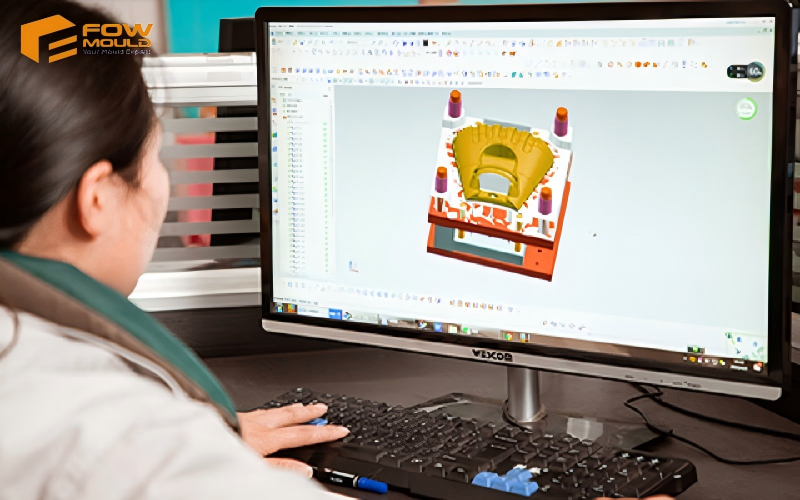
Designers need to use professional 3D software (such as UG/NX, SolidWorks, Creo, etc.) and perform mold flow analysis to simulate plastic flow, cooling, and shrinkage within the mold, thereby identifying and solving potential defects such as sink marks, warpage, weld lines, and air traps in advance.
The Design Process Of Plastic Mold
Generally, the plastic mold design process includes multiple key steps aimed at ensuring the mold can efficiently and accurately produce plastic parts that meet requirements.
Step 1: Part Analysis and Requirement Gathering
The design process begins with a thorough analysis of the plastic part to be molded. Designers need to conduct a comprehensive analysis of the product’s structure and function, determine material properties, wall thickness uniformity, and any complex geometries.
Step 2: Material Selection
Next, select suitable plastic materials based on product needs, considering their shrinkage rates and flow characteristics.Injection molding uses thermoplastics and some thermosets,common thermoplastics include nylon, polyethylene, and polystyrene.
Injection molded parts can be enhanced with additives to achieve specific properties. For instance, fiberglass can be incorporated into pellets at ratios ranging from 10% to 30% to improve strength and stiffness.
Mixing existing materials with alloys or blends of previously developed materials allows product designers to choose from a wide variety of materials to find the one with exactly the right properties.
Step 3: Mold Conceptualization and Layout
Based on the part analysis, designers create the initial mold layout, defining the number of cavities, parting line, gate type and location, runner system, and ejection mechanism. The choice between single cavity molds or multi-cavity molds depends on production volume and cost considerations.
Step 4: Mold Flow Simulation
Using specialized software, mold flow analysis simulates the filling, packing, and cooling stages within the mold.
This helps identify potential defects such as air traps, weld lines, sink marks, and short shots. The simulation guides optimization of gate placement, runner design, and cooling channel layout to ensure uniform filling and minimize shear heat burning.
Step 5: Detailed Mold Design
The mold components, including core and cavity, cooling channels, ejector pins, and venting systems, are precisely designed using 3D CAD software. Designers ensure uniform wall thickness and incorporate draft angles to facilitate part ejection.
Tooling surfaces are specified based on required surface finish and durability, often selecting hardened steel for high volume production.
Step 6: Prototype Mold Building and Testing
Upon completing the design, prototype molds are usually made for trial molding to verify design rationality and production efficiency, discovering and resolving any issues.Adjustments can be made to address issues such as excessive shear heat or uneven cooling before committing to hardened steel molds.
Step 7: Final Mold Manufacturing
After successful prototyping, the final mold is manufactured using hardened steel and incorporates optimized hot runner systems if applicable. The mold undergoes heat treatment and surface finishing to enhance durability and part quality. Cooling channels and ejector systems are finalized for efficient production.
Step 8: Mold Validation and Production Start
The completed mold undergoes validation runs to confirm dimensional accuracy, surface finish, and cycle efficiency. Injection molding parameters are fine-tuned to balance injection pressure, speed, and cooling time.
Once validated, the mold enters high volume production, delivering consistent quality parts with minimized defects.
This systematic design process ensures that plastic mold design meets both functional and economic requirements, enabling efficient high volume production of quality plastic parts.
Basic Components Of A Plastic Injection Mold
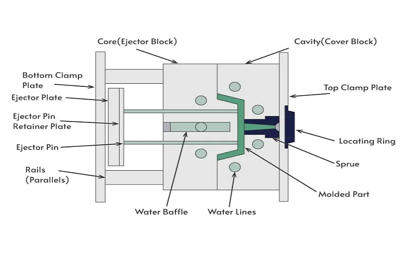
A plastic injection mold consists of several essential components that work together to shape molten plastic into the desired part. Injection molds are capable of producing over 100,000 parts throughout their lifespan. A thorough understanding of these components is essential for effective plastic mold design.
Mold Cavity and Core
The mold cavity is the hollow space that defines the external shape of the molded part, while the core forms the internal features. These two halves come together to create the part geometry. The precision and surface finish of the cavity and core directly influence the quality and appearance of the final product.
Gate and Runner System
Molten plastic resin flows from the injection molding machine through the sprue into the runner system, which distributes the plastic to one or more gates. For optimal filling, gates system should be positioned in the thickest sections of the part. Among gate types, the edge gate is the most commonly used design.
Cooling System
Cooling channels are integrated within the mold plates to remove heat from the molten plastic after it fills the cavity. Standard cooling channels are straight lines drilled through the mold base.Conformal cooling channels follow the cavity surface for better heat removal.
Efficient cooling design is crucial as it accounts for 60-70% of the injection molding cycle time and affects part dimensional stability and warpage.
Ejection System
After the plastic solidifies, the mold opens, and ejector pins or plates push the part out of the mold. Proper ejection design prevents part damage and ensures smooth production cycles.
Mold Base and Plates
The mold base provides the structural support for all components and includes the A-side (cavity side) and B-side (core side) plates. These plates must be precisely machined and heat treated to withstand high clamping forces and repeated cycles.
Vent System
Vents allow trapped air and gases to escape during injection, preventing defects such as burns or incomplete filling. Proper venting design is essential for high-quality molding.
Each component must be carefully designed and integrated to optimize the injection molding process, reduce defects, and extend mold life. Advanced mold design often involves simulation tools to analyze flow, cooling, and stress distribution within these components.
Considerations Of Injection Mold Design
Injection mold design requires careful consideration of multiple factors to ensure the production of high-quality plastic parts while maintaining efficiency and cost-effectiveness.
Optimizing plastic mold design should adhere to the principles of Design for Manufacturability (DFM).Key considerations include:
Material Characteristics
Different materials shrink differently during injection molding, which directly affects mold size compensation and final part accuracy. Material flowability determines how molten plastic fills the mold cavity, impacting gate location and runner design.
Thermal stability and heat conductivity relate to cooling system design to ensure even cooling and reduce deformation. Mechanical properties influence mold structure parameters like wall thickness, ribs, and draft angles.
Gate Location and Type
Proper gate location is essential to ensure uniform filling and minimize defects such as weld lines and air traps. Gates are typically placed in the thickest sections of the part to facilitate smooth flow.
Various gate types, including hot tip gates, tunnel gates, and edge gates, offer different advantages depending on part geometry and production volume.
Wall Thickness and Uniformity
Ideal wall thickness typically ranges from 2mm to 4mm, though thin wall injection molding techniques can achieve walls as slender as 0.5mm.
For plastics with high shrinkage rates, wall thickness deviations should not exceed 10%. Maintaining consistent wall thickness is critical to avoid issues like sink marks, warpage, and uneven cooling.
Parting Line Design
The parting line, where the two halves of the mold meet, affects mold opening, ejection, and the appearance of the final part. Strategic placement minimizes visible seams and facilitates gate removal. Consideration of a and b sides of the mold during parting line design ensures proper ejection and reduces molded-in stress.
Cooling System Optimization
Efficient mold surface cooling is vital for reducing cycle time and improving part quality. Cooling channels should be designed to provide uniform temperature distribution, preventing warpage and shrinkage.
Advanced techniques like conformal cooling and the use of tool steel or aluminum molds affect cooling efficiency and mold lifespan.
Draft Angles and Surface Texture
Draft angles facilitate part ejection by preventing drag marks and damage. The required draft increases with textured surfaces, as the texture can act like microscopic undercuts. A minimum draft angle of 2° is recommended for vertical walls, with an additional 1° of draft added for every 25 mm of feature height.
Tolerance and Precision Requirements
Precision molds achieve tight tolerances typically ranging from ±0.01 to ±0.05 mm, ensuring high dimensional accuracy and consistency for critical applications.
However, precision molds generally cost 2-3 times more than standard molds due to the increased complexity, materials, and validation processes involved.
By integrating these considerations, injection mold design can effectively produce plastic parts with optimal physical properties, dimensional accuracy, and surface finish, while controlling costs and maximizing production efficiency.
The Key Role of Injection Molding Machine Parameter Optimization In Plastic Mold Design
Mold design must not only consider the structure of the mold itself and the cooling system but also must be optimized in conjunction with the process parameters of the injection molding machine.
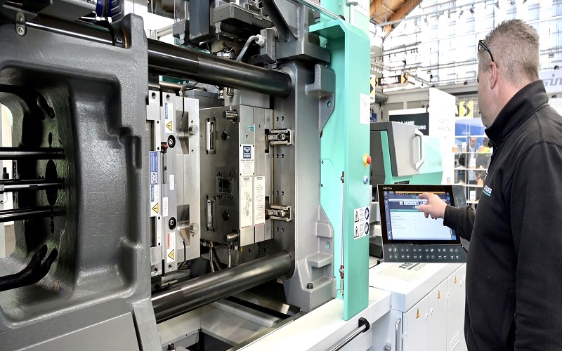
Injection molding machines can exert clamping forces ranging from 5 to 9,000 tons, depending on the size and complexity of the part.
If the plastic material is harder, more injection pressure is required to fill the mold, thus a greater clamping force is needed to keep the mold closed.
Precise control of injection speed, injection pressure, and new shot nozzle temperature is essential for achieving consistent part quality and minimizing defects.
The injection speed set must be optimized to balance filling time and material shear. Too much shear heat generated during injection can degrade the molten plastic, causing burn marks and negatively affecting the mechanical properties of the part.
Additionally, the injection unit and injection ram must be properly calibrated to ensure that molten plastic enters the mold cavity smoothly and fills it uniformly.
Adjusting patterns injection speeds and flow direction helps reduce high molded in stress and avoid issues such as short shots or plastic shrinks.
Proper management of these parameters leads to improved surface finish, dimensional accuracy, and overall production efficiency.Before making a choice, please consider the desired product characteristics and the performance of the injection molder.
Common Problems In Plastic Mold Design And Production Process
Plastic mold design and manufacturing involve complex processes where various issues can arise, impacting the quality, efficiency, and cost of production. Understanding these common problems is essential for designers and engineers to implement effective solutions and optimize the injection molding process.
Warping and Distortion
Warping occurs when different sections of a molded part cool and shrink unevenly, causing the part to bend or twist. This is often due to non-uniform wall thickness, improper cooling channel design, or inconsistent material flow. Warping can lead to dimensional inaccuracies and assembly issues.
Sink Marks
Sink marks are depressions or dimples on the surface of molded parts, typically appearing in thicker sections where the material cools slower than surrounding areas. They result from volumetric shrinkage as the plastic solidifies. Designing uniform wall thickness and adding ribs or coring can help mitigate sink marks.
Weld Lines and Knit Lines
Weld lines form where two flow fronts of molten plastic meet and fail to fuse properly, creating weak spots and visible lines on the part surface. These can compromise both the aesthetics and mechanical strength of the part. Proper gate placement and optimized injection parameters help reduce weld lines.
Short Shots
Short shots occur when trapped air inhibits material flow. Causes include insufficient injection pressure, improper gate size or location, and trapped air. Mold flow simulation and venting improvements can prevent short shots.
Drag Marks and Ejection Issues
Drag marks are surface scratches caused when parts are ejected without sufficient draft angles, leading to friction against the mold surfaces.
Inadequate ejection system design can also cause part deformation or damage during removal. Incorporating proper draft angles and efficient ejector mechanisms improves ejection quality.
Mold Wear and Maintenance
Repeated injection cycles cause wear and tear on mold components, affecting part dimensions and surface finish over time. Selecting appropriate mold materials, such as hardened steel, and implementing preventive maintenance schedules extend mold life and ensure consistent production.
By proactively addressing these common problems through thoughtful design, simulation, and process control, manufacturers can achieve higher quality plastic parts, reduce production costs, and shorten lead times.
Conclusion
In summary, plastic mold design is a vital process that directly influences the quality, efficiency, and cost-effectiveness of injection molded parts.
By carefully considering material properties, mold structure, cooling systems, gate placement, and machine parameters, designers can minimize common defects and optimize production. Advanced tools like mold flow analysis and prototype testing further enhance design accuracy and reduce risks.
With a systematic approach and attention to detail, manufacturers can achieve high-quality, precise, and durable plastic components that meet both functional and aesthetic requirements, supporting successful mass production.