
Undercut design in injection molding is a crucial technique for manufacturing complex plastic parts. Undercuts not only enhance the functionality and aesthetics of the parts but also impose higher demands on mold design and the production process.
This article provides a comprehensive overview of the basic concepts, design tips, and common applications of injection molding undercuts, helping designers and engineers better master this key process to find the best solution for your part.
What Are Undercuts In Injection Molding Process?
Undercut molding is an important process for manufacturing hooks, grooves, and other elements that have a direct effect on the functionality of parts. These undercuts can be internal or external and often cause the molded parts to be stuck during mold opening, increasing the complexity of mold design and manufacturing.
In the plastic injection molding process, undercut designs are widely used to produce parts with complex shapes and functions, such as components with clips, locks, side holes, threads, and other features.
Proper undercut design not only enhances the functionality and aesthetics of injection molded parts but also ensures structural strength and assembly performance.
However, the presence of undercuts usually increases production costs and manufacturing difficulty. Mold designers need to address these challenges using various techniques based on the specific requirements of the injection molding project, the properties of the plastic material, the part geometry, and the mold’s parting line placement.
Common solutions include side actions, hand-loaded inserts, and deformation-based ejection for flexible and elastic materials.
Mastering key undercut design techniques is essential for optimizing the injection molding process, reducing production costs, and improving part quality.
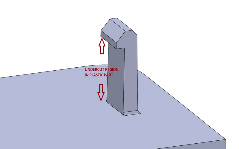
Types Of Undercuts
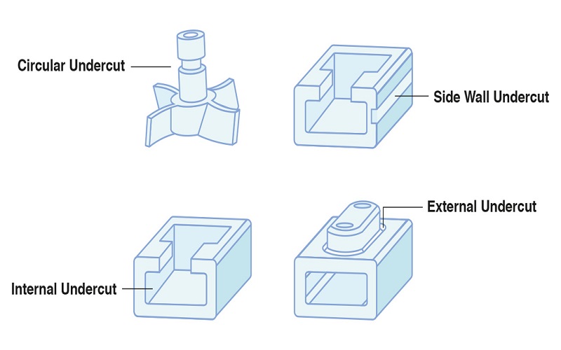
Undercut injection molding is a critical procedure in the manufacture of complex components. can be broadly categorized based on their location and the challenges they pose during the molding process.
Understanding the types of undercuts helps designers choose the most effective manufacturing approach and tooling solutions.
External Undercuts
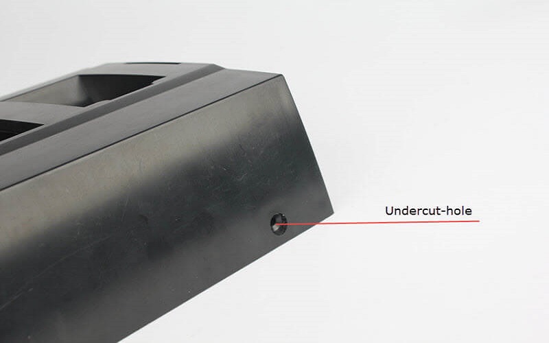
External undercuts are features that protrude outward from the main body of the part, such as clips, hooks, ribs, or side holes. These external features often require specialized mold components like side action cores or cam slides to enable the mold to open without damaging the part.
External undercuts are common in plastic housing for consumer electronics and medical devices, where secure connections and aesthetic requirements are critical.
Internal Undercuts
Internal undercuts are recessed features within the part, such as internal threads, grooves, or cavities that trap the molded part inside the mold. These require more complex tooling solutions, including collapsible cores or lifters, to allow the part to be ejected without damage.
Internal undercuts are frequently found in applications like oxygen delivery units and other medical devices where intricate geometries and internal features are necessary.
Vertical Threads
Vertical threads are a specialized type of internal undercut commonly used to create screw-like features directly in the molded part. These threads provide secure connections without the need for additional fasteners.
Manufacturing vertical threads typically involves unscrewing mechanisms or collapsible cores to release the part from the mold safely.
Interlocking Features
Interlocking features are undercuts designed to enable parts to snap-fit or lock together securely. These external or internal features are essential for product assembly and are widely used in consumer electronics, automotive components, and packaging.
Designing interlocking features requires careful consideration of material flow, draft angles, and mold design to ensure a cost-effective solution.
Complex Geometries and Intricate Designs
Some undercuts involve complicated designs with multiple undercut features, combining both internal and external elements.
These require advanced manufacturing processes, including the use of side actions, collapsible cores, and sometimes secondary operations like CNC machining or drilling to achieve the desired part geometry. The more complex the undercut features, the higher the associated costs and tooling complexity.
By classifying undercuts into these types, designers and manufacturing partners can better strategize the molding process, select appropriate materials, and implement effective mold designs to master undercuts efficiently and economically.
Technical Solutions For Handling Injection Molding Undercuts
Handling undercuts in injection molds is a complex and technically demanding task. Designers and engineers typically employ various technical solutions depending on the type of undercut and material characteristics to ensure smooth part ejection while maintaining product functionality and aesthetics.
Side Actions
Side actions are a common method for addressing external undercuts. They involve incorporating sliding side cores in the mold that move horizontally or vertically perpendicular to the mold opening direction, allowing the undercut areas to be released.
Side actions require movement perpendicular to the mold opening and have size limitations, with a maximum width of 8.419 inches and height of 2.377 inches. They are especially suitable for rigid materials such as nylon and polycarbonate, as the rigidity helps prevent parts from sticking during side core retraction.
Bump-Offs
For flexible materials like TPE and LDPE, bump-offs offer a cost-effective solution. By designing smooth-radius protrusions, parts can elastically deform during ejection, allowing them to clear undercuts without damage. This approach requires controlling airflow and injection pressure to avoid part damage during ejection.
Hand-Loaded Inserts
Hand-loaded inserts are ideal for low-volume production. Machined metal inserts are placed in the mold cavity to block plastic flow into certain areas, forming undercuts. After molding, the inserts eject with the part and are manually removed for reuse.
This method simplifies mold construction and lowers tooling costs, especially for complex or internal undercuts. However, manual handling increases cycle time, and operators must wear heat-resistant gloves for safety when dealing with high temperatures.
Typically, inserts should be no smaller than 0.500 inches square for ease of handling and not excessively large to avoid operator strain.
Collapsible Cores and Ejector Systems
For internal undercuts, collapsible cores and ejector systems are common solutions. Collapsible cores retract during mold opening to release internal features such as threads and complex cavities. Ejector pins assist in pushing the part out of the mold. Proper ejector pin placement is critical to avoid surface damage.
Two-Half Mold Design Optimization
Optimizing the mold’s parting line placement can transform some undercuts into features along the parting line, reducing the need for complex side actions or inserts. Adjusting the parting line requires considering part geometry, material flow, and cooling performance to ensure good mold sealing and smooth ejection.
Secondary Operations
When undercut designs are overly complex or volumes are low, secondary machining operations such as milling or drilling can be used post-molding. This avoids complex mold tooling and reduces initial mold costs but increases production time and labor expenses.
By combining these technical solutions, designers can effectively control and optimize undercut features in injection molds, minimizing production costs and manufacturing difficulty while achieving high-quality molded parts and enhanced product performance.
Designing Undercuts For Injection Molded Parts
Designing undercuts in injection molded parts requires considering multiple factors to ensure both functionality and manufacturability. The key points for successful undercut design are as follows:
Proper planning of the parting line location
Adjusting the parting line to intersect with the undercut features can effectively reduce the need for complex side actions and mold components, thereby simplifying mold design and lowering costs. However, parting line adjustments must also take into account part geometry, molten plastic flow, and other factors.
Ensuring sufficient draft angles
Appropriate draft angles (typically at least 3 degrees for shutoffs) should be applied to the undercuts and related features to allow smooth ejection when the mold opens, preventing damage or scratching of the part surface.
Selecting suitable ejection methods
For external undercuts, side actions or cam slides can be used to achieve lateral ejection. Side actions are limited to 8.419 inches wide by 2.377 inches high and work best with more rigid the material such as nylon and polycarbonate.
For internal undercuts, collapsible cores or lifters can assist in ejection. Additionally, for flexible materials, bump-offs that rely on elastic deformation provide an economical and effective solution.
Finally, close communication with mold manufacturers during the design process is essential. Considering production volume, mold cost, and manufacturing cycle time along with other factors helps choose the best design approach.
Parameter | Recommended Range |
|---|---|
Undercut Depth | 0.5 to 2.5 mm (maximum not exceeding 50% of wall thickness) |
Undercut Angle | External undercut ≤ 5°, Internal undercut ≤ 8° |
Undercut Width | ≥ 1.5 times the wall thickness |
Draft Angle | At least 0.5° to 2° around the undercut |
Minimum Wall Thickness | 1.0 mm (engineering plastics) to 1.5 mm (general plastics) |
Early-stage design reviews and simulation analyses can effectively prevent potential undercut issues, improving part quality and production efficiency.
In summary, successful undercut design in injection molding requires comprehensive consideration of parting line layout, sufficient draft, ejection mechanisms, material properties, and production needs.
Balancing these factors appropriately enables the creation of high-quality injection molded parts that meet functional requirements and are easy to manufacture.
Common Applications Of Undercut Injection Molding
Undercut injection molding finds extensive use across various industries due to its ability to create complex and functional features in plastic parts. Some of the most common applications include:
Medical Devices
Many medical devices require intricate geometries for functionality and safety, such as oxygen delivery units, diagnostic equipment, and surgical tools. Undercuts enable the integration of clips, locking mechanisms, and internal channels essential for these devices.
Consumer Electronics
Plastic housings for consumer electronics often incorporate undercuts to accommodate buttons, switches, and access points. These features enhance usability and aesthetics while maintaining durability.
Automotive Components
The automotive industry uses undercuts to produce parts with interlocking features, seals, and complex threads. These components contribute to vehicle safety, performance, and assembly efficiency.
By leveraging undercut injection molding, manufacturers can produce parts that combine complex design with high performance, meeting the rigorous demands of modern products.
Conclusion
Injection molding undercuts are essential design features that enable the creation of complex, functional, and aesthetically pleasing plastic parts across various industries.
While they introduce challenges in mold design and production, understanding the types of undercuts and employing appropriate technical solutions can effectively manage these complexities.
Careful consideration of part geometry, material properties, draft angles, and parting line placement is crucial for optimizing manufacturability and minimizing costs.
By mastering undercut design principles and collaborating closely with mold manufacturers, designers can achieve high-quality injection molded parts that meet both functional and production requirements, ultimately enhancing product performance and market success.