Injection compression molding is recognized as one process that effectively merges the advantages of injection molding and compression molding, optimizing the manufacturing of high-precision plastic components.
It is designed to produce high-quality plastic parts with improved dimensional accuracy, reduced internal stresses, and excellent surface finish.
Injection compression molding is frequently used for optical components, automotive parts, and electronics packaging.
This article provides a comprehensive guide to injection compression molding, covering its technical definition, step-by-step process sequence, advantages and limitations, equipment and tooling requirements, suitable materials, and real-world applications across industries.
What Is Injection Compression Molding?
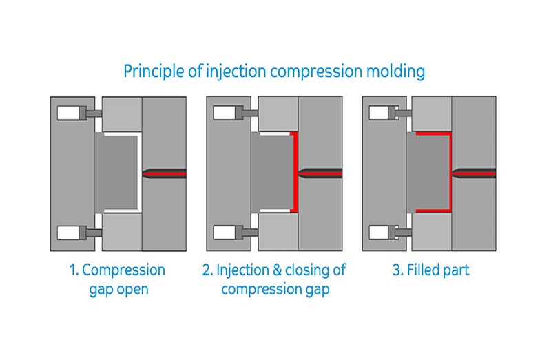
Injection compression molding is a hybrid manufacturing process where molten plastic is injected into a partially open mold that then closes to compress and fill the cavity.
It combines the principles of injection molding and compression molding, enabling the production of plastic parts with higher quality and performance.
In this process, molten resin is first injected into a partially closed mold, allowing the material to flow under lower pressure and shear stress. Subsequently, the mold fully closes, compressing the molten resin to precisely and uniformly fill the cavity.
Compared to traditional molding methods, injection compression molding minimizes excess material and the formation of parting lines, resulting in parts with superior surface finish and dimensional accuracy.
Injection compression molding is especially suitable for producing thin-walled parts, large flat components, and parts requiring high optical clarity or complex surface textures.
It accommodates various materials, including thermoplastics and thermosets materials, making it widely applicable in industries such as automotive, electronics, packaging, and medical devices.
By combining the advantages of injection molding and compression molding, injection compression molding can produce parts of higher quality with shorter production cycles and better performance than either process alone.
Detailed Injection Compression Molding Process
The injection compression molding process mainly consists of the following steps:
Step 1: Mold Preparation and Partial Opening
The cycle begins with the tool heated or cooled to material-specific temperatures,the clamping unit positions the moving half with a precisely controlled gap, usually 0.5–4 mm depending on the target wall thickness.
High-resolution encoders ensure platen parallelism within microns, preventing uneven compression that would create thickness variations in the molded part.
Step 2: Injection Phase
The screw delivers polymer melt at reduced speeds and pressures compared to conventional injection. Where standard injection molding might require 1500–2000 bar, injection compression operates at 500–1000 bar because the partly open cavity presents significantly less flow resistance.
The injection molder fills the cavity to a preset volume or time threshold without fully pressurizing the mold cavity.
Step 3: Compression Phase
Once the injected volume reaches its target, the compression process activates. The clamping unit or internal compression elements close the remaining gap, forcing the plastic melt to spread across the entire cavity surface.
This compression stroke—typically 1–6 mm executed within 100–300 ms—finalizes part thickness while replicating fine surface details with high fidelity.
Step 4: Holding and Packing
The compression step itself replaces much of the conventional holding pressure phase. As the mold fully closes, uniform pressure distribution packs the material naturally, compensating for volumetric shrinkage without the high-pressure packing cycles that create stress in standard injection molding.
Step 5: Cooling Process
Controlled cooling follows, often utilizing conformal cooling channels for thin-wall parts. Typical cooling times range from 10–30 seconds depending on part size and wall thickness.
Temperature uniformity during this phase is critical for achieving the dimensional accuracy that makes injection compression attractive for precision applications.
Step 6: Demolding and Ejection
Ejection requires careful consideration for large-area or delicate components. Uniform compression during the previous phases helps maintain flatness tolerances under 0.1 mm/m, but ejectors must be optimized to preserve this precision during part removal.
The full cycle time typically spans 20–60 seconds, balancing quality gains against slight extensions from synchronization requirements.
Equipment Requirements And Mold Design For Injection Compression Molding
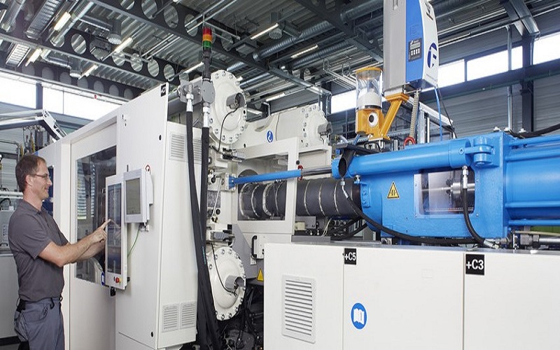
Although the successful injection compression molding process is based on traditional injection molding machines, it requires higher precision and specialized mechanical equipment and mold improvements.
Machine Capabilities
Modern injection molding machines configured for injection compression need high-precision clamping control with sub-micron position accuracy. Synchronized injection and mold movement is essential—the injection profile must coordinate precisely with platen motion.
Real-time platen parallelism monitoring ensures uniform compression across large cavities, while high-resolution position encoders enable the closed-loop control necessary for consistent results.
The innovative energy recovery systems in modern injection molding machines can collect and reuse braking energy, further enhancing energy efficiency during the injection molding process.
Compression-Capable Tooling
Mold design for injection compression involves movable cores or inserts, floating cavity plates, integrated compression rings, and configurations compatible with stack molds for high-output packaging.
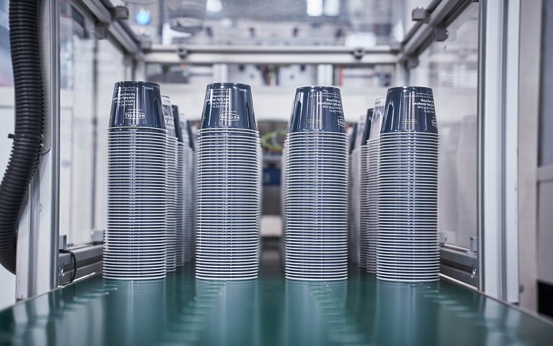
For thin-wall containers around 0.4 mm, stack molds with 100+ cavities achieve the production volume economics that justify investment in this technology.
Compared to conventional injection, machines require 30–50% less tonnage—for example, 500 tons versus 1000 tons for a 1 m² panel.
This reduction in lower clamping forces translates to smaller equipment investments and reduced floor space requirements. However, initial mold costs rise 20–40% due to the added kinematics and precision components.
Runner System and Gate Design
Gate design considerations differ from standard injection molding. Larger gates—often 20–50% wider than conventional designs—leverage the compression phase to achieve complete filling.
Fan gates or ring gates work well for many applications, while edge gating approaches suit large panels where the compression step helps minimize weld lines and sink marks.
Accurate venting becomes critical during the rapid compression phase. Venting slots typically 0.01–0.03 mm deep allow air to escape without creating flash, particularly important for large flat plates and clear parts where trapped air would cause burns or voids.
Attribute | Conventional Injection | Injection Compression |
|---|---|---|
Clamping Force | Higher (baseline) | 30–60% lower |
Peak Injection Pressure | 1500–2000 bar | 500–1000 bar |
Minimum Wall Thickness | ~0.8 mm typical | 0.3–0.4 mm achievable |
Internal Stress Levels | Higher | Significantly reduced |
Tooling Costs | Baseline | 20–40% higher |
Position Control | Standard | Sub-micron precision |
Benefits Of Injection Compression Molding
Injection compression molding is a combination of injection molding and compression molding that enables the manufacture of high-precision plastic parts with excellent dimensional stability and superior mechanical properties.
Enhanced Part Quality and Dimensional Accuracy
This process injects molten material into a partially open mold, which then closes and compresses the material to achieve a more uniform pressure distribution.
This significantly reduces internal stresses and warpage, which is particularly beneficial for optical components by minimizing birefringence effects.
Lower Energy and Equipment Costs
Injection compression molding can process highly viscous materials with high repeatability. Compared to traditional injection molding, it operates at lower clamping forces and injection pressures, helping to reduce energy consumption and improve unit cost competitiveness.
Broader Material Capabilities
Moreover, injection compression molding is suitable for various molding materials, including thermoplastic compounds and thermosetting polymers, broadening its applications in the plastics industry.
Thin-Wall Optimization
Injection compression molding reduces residual stress and improves surface finish, making it ideal for thin-wall, high-precision, or large parts. It is widely used in optical components, automotive parts, and electronics packaging.
By optimizing both the injection process and compression steps, injection compression molding achieves good dimensional accuracy and surface quality, meeting the stringent performance requirements of advanced manufacturing.
Limitations of Injection Compression Molding
Although injection compression molding combines the advantages of injection molding and compression molding to produce high-precision, low-stress plastic parts, it still has some limitations.
First, this process requires high precision in equipment and molds, typically needing specialized high-precision injection molding machines and complex mold design and manufacturing, resulting in a relatively large initial investment cost.
Second, the process parameters of injection compression molding are more complex to control, requiring strict synchronization of injection speed and mold closing action, making operation more difficult and demanding high process stability.
In addition, the cycle time of this process is usually slightly longer than that of traditional injection molding, which may affect efficiency in high-volume production.
Finally, although injection compression molding is suitable for various materials, it can be challenging to mold certain highly filled or high-viscosity composite materials, which may require special equipment or improved process solutions.
Overall, injection compression molding is more suitable for manufacturing mid- to high-end products with high requirements for dimensional accuracy, surface quality, and internal stress, while traditional injection molding still holds advantages for low-cost, high-volume ordinary parts.
Applications Of Injection Compression Molded Parts
Injection compression molding is frequently used for optical components, automotive parts, and electronics packaging, with applications spanning multiple industries where its unique capabilities deliver value.
This molding technique excels in producing parts that require intricate details and uniform distribution of material, making it ideal for manufacturing complex parts with thin walls and large surface areas.
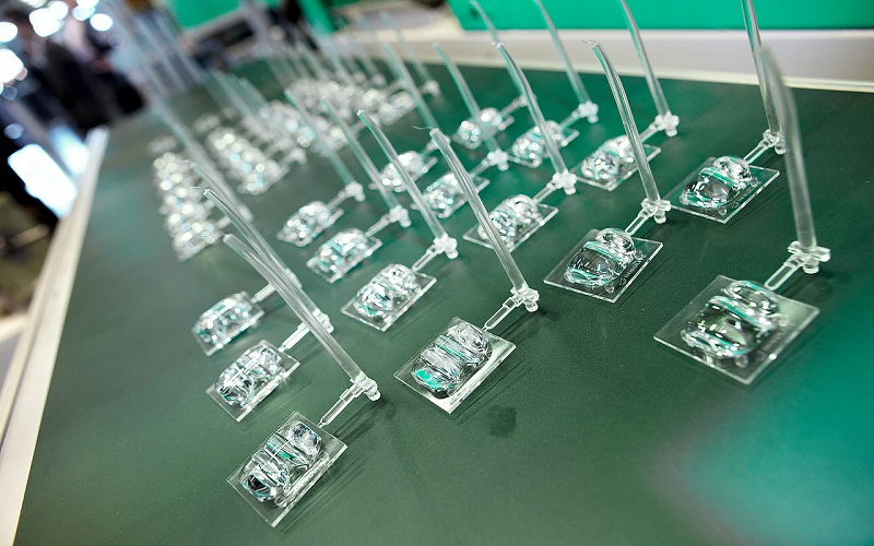
Optical Parts
In the optical industry, injection compression molding is preferred for lenses and light-guiding components due to its ability to reduce internal stresses and minimize birefringence effects, which are critical for maintaining optical clarity.
The process’s ability to replicate intricate details with high precision ensures superior surface finishes and dimensional accuracy, essential for high-performance optical devices.
Automotive Components
Automotive applications benefit from this process by producing lightweight, durable parts with improved dimensional stability.
Injection compression molding allows for lower injection pressures and reduced residual stresses, which enhance the mechanical properties and longevity of automotive components such as instrument panels, door panels, and lighting covers.
Electronics Packaging
In electronics packaging, the technique supports the production of thin-walled housings and components that require precise dimensional control and excellent surface quality.
The uniform pressure distribution during compression reduces molding defects such as warpage and sink marks, ensuring reliable protection and insulation of sensitive electrical components.
Beyond these sectors, injection compression molding is increasingly applied in medical devices, consumer goods, and packaging industries.
Additionally, the process aligns with circular economy principles by facilitating the use of recyclable materials and reducing waste through efficient material usage.
Comparisons Between Injection Compression Molding And Traditional Injection Molding
The core differences between Injection Compression Molding (ICM) and Conventional Injection Molding (CIM) mainly lie in mold cavity control methods, molding pressure, internal stress levels, suitable part characteristics, and process flow.
Injection compression molding injects molten plastic into a partially open mold, then closes the mold to compress the plastic, achieving more uniform pressure distribution and higher dimensional accuracy.
In contrast, conventional injection molding injects molten material at high pressure into a fully closed mold, resulting in uneven pressure distribution that can cause internal stresses and deformation.
Injection compression molding is suitable for manufacturing thin-walled, large-area parts with high optical performance requirements, while conventional injection molding is better suited for parts with complex shapes and high production efficiency.
Regarding the process flow, injection compression molding requires precise synchronization of injection speed and mold closing, demanding higher equipment capabilities, but it significantly reduces residual stress and warpage, improving part quality.
Conventional injection molding is a more mature process with simpler operation, ideal for mass production.
Injection compression molding also shows advantages in energy saving and emission reduction due to its lower injection pressure and clamping force requirements, reducing equipment energy consumption and mold wear, while enabling material savings and lightweight design.
Overall, injection compression molding combines the advantages of injection molding and compression molding, providing a high-precision, low-stress, energy-efficient molding solution, especially suitable for applications with high demands on part quality and performance.
Comparison Dimension | Conventional Injection Molding (CIM) | Injection Compression Molding (ICM) |
|---|---|---|
Pressure Distribution | Gradient decreasing from gate to end | Uniform throughout compression phase |
Injection Pressure | High (100–200 MPa) | Low (about 30–70% of conventional) |
Clamping Force Requirement | High | Significantly reduced (up to 75%) |
Flow Path | Long, high length-to-thickness ratio (L/T) | Short, spread filling |
Flow Uniformity | Front-driven, prone to flow marks | Overall compression, stable flow front |
Conclusion
Injection compression molding effectively combines the strengths of injection and compression molding to produce high-quality plastic parts with superior dimensional accuracy, reduced internal stresses, and excellent surface finishes.
This process is especially beneficial for thin-walled, large, and complex components used in industries such as optics, automotive, and electronics.
While it requires precise equipment and mold design, the advantages in part quality, energy efficiency, and material savings make injection compression molding a valuable manufacturing method for high-performance applications.
FAQ
Is injection compression molding suitable for prototyping or mainly for high-volume production?
While injection compression is most economical for medium- to high-volume production runs spanning tens of thousands to millions of parts, it can serve prototyping when final parts demand thin walls or optical quality that conventional injection cannot easily provide.
Prototype tooling can use simplified approaches like aluminum molds with basic compression mechanisms, though costs still exceed standard prototype injection molds.
For low-volume prototyping of parts without strict thin-wall or optical requirements, conventional injection remains more practical.
Can fiber-reinforced or composite materials be processed by injection compression molding?
Short-glass and mineral-filled thermoplastics up to 30% loading process successfully, with the compression step improving fiber orientation uniformity and reducing warpage in flat parts. Carbon fibers and glass fibers both work within these limits.
However, very high fiber contents above 40% or highly viscous composite systems may require specialized tooling, and traditional compression molding or long-fiber processes may prove more suitable.
Sheet molding compound applications typically favor compression molding over injection compression.
How do I know if my part design will benefit from injection compression molding?
Parts with large projected area, thin walls between 0.3–0.8 mm, high optical demands, or strict flatness requirements are prime candidates.
Evaluate maximum flow length-to-thickness ratio (L/T above 200:1 favors injection compression), allowable internal stress level, and target machine tonnage.
If conventional injection requires high pressure or clamp force causing concerns, or if stress analysis reveals unacceptable birefringence, injection compression deserves evaluation.
Does injection compression molding always reduce cycle time compared to standard injection molding?
Cycle time may be similar or slightly longer—often adding 5–10 seconds—because of the controlled compression step and synchronization requirements. However, lower packing and potentially faster cooling from thinner walls can offset some extension.
The primary benefits are typically quality improvements, material savings through thinner walls, and lower clamp force rather than pure cycle-time reduction. For high-precision and thin-wall parts, the quality advantages justify any minor cycle extension.
What special measurements or testing methods are used to validate injection compression molded parts?
Polarized-light stress analysis verifies reduced internal stresses and birefringence, particularly critical for transparent components and lenses. 3D scanning confirms flatness specifications, typically targeting ±0.05 mm on large panels.
Thickness mapping across the part surface validates uniform compression, while cavity pressure curve analysis confirms the compression phase operates as intended—look for uniform 300–600 bar plateaus rather than pressure spikes.
These measurements during production qualification ensure the upper mold and lower mold interact correctly throughout the molding cycle.