The design of lifters in injection molding is a critical aspect to ensure the smooth demolding of complex plastic parts.
As mechanical components within the mold, lifters effectively release molded parts with internal undercuts, threads, and other intricate features, enhancing ejection efficiency and product quality.
With the advancement of the injection molding process, the design and application of lifters have been continuously optimized, helping manufacturers achieve high precision and high efficiency in production.
This article will delve into the role of injection molding lifters, design principles, and their practical applications in molds, assisting engineers and mold makers in better understanding and utilizing this essential mold component.
What Is Injection Molding Lifter?
An injection molding lifter is a key mechanical component installed in a plastic injection mold, primarily used to assist in the smooth ejection of complex parts during the demolding process.
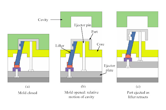
It performs a combined vertical and horizontal motion within the mold cavity, lifting molded parts with internal undercuts, threads, and other intricate features, particularly those ensuring the parts are safely released from the mold core without damage.
Unlike sliders used for ejecting external undercuts, lifters move upward and inward (or outward) simultaneously as the mold opens, helping the parts to automatically disengage from the mold cavity for a smooth, scratch-free demolding process.
The lifter’s motion is driven by the ejector plate of the injection molding machine, combining vertical movement along the mold opening direction with a certain angled motion.
This makes lifters particularly suitable for demolding plastic parts with internal holes, slender ribs, and complex internal geometries.
The major advantage of a mold lifter is that it helps to improve the efficiency of manufacturing processes by automating the part removal process, which drastically reduces turnaround time.
At the same time, the design must ensure that lifters have sufficient strength to resist injection pressure and integrate seamlessly with the ejector system to achieve smooth demolding operations, avoiding part warping and surface defects.
Types Of Injection Molding Lifter
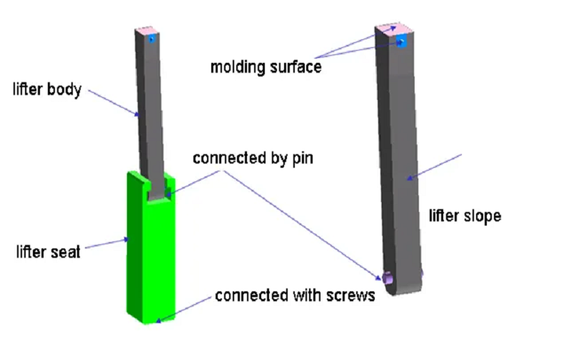
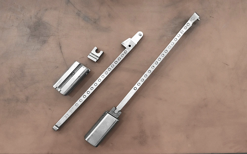
Injection molding lifters are mainly divided into two types based on their structural form: integral and non-integral.
According to the shape of the molding head, they can be further subdivided into common variants such as cylindrical and T-shaped or blade-shaped.
The choice of different structures directly affects the mold’s compactness, strength, machining difficulty, maintenance convenience, and the size of the applicable plastic parts.
Integral Lifters
Integral lifters are single-unit components built directly into the mold. They are strong and durable, ideal for smaller parts with detailed internal features. Their solid construction ensures precise alignment and reliable performance over long production runs.
Non-Integral Lifters
Non-integral lifters are made of separate units assembled into the mold. They offer flexibility for replacement and adjustments, suitable for larger parts or molds needing frequent changes. Though cost-effective, they require careful alignment and wear management.
Cylindrical Lifters
Cylindrical lifters are common and simple in shape, easy to make and maintain. They work well for parts with basic internal features, providing smooth vertical and angled movement.
T-Shaped Lifters
T-shaped lifters are used for bigger parts or when more precision is needed. Their shape offers better contact with the part, improving stability during ejection and handling complex internal details effectively.
By selecting the appropriate type of injection molding lifter and carefully considering its design and materials, manufacturers can optimize the molding process, reduce cycle times, and achieve superior part quality even with the most challenging internal features.
Key Components And Functionalities Of Mold Lifter Mechanism
An injection molding lifter mechanism consists of several critical components that work together to ensure smooth and efficient ejection of molded parts with complex internal features.
Understanding these components helps in designing lifters that provide reliable operation and high-quality part production.
Lifter Rod
The lifter rod is the main part that directly contacts the molded product. It is designed to match the geometry of the internal undercuts or complex shapes that need to be released. The rod moves both vertically and at an angle during the ejection process, lifting the molded part off the mold core.
Guide Pin
The guide pin ensures proper alignment and stability of the lifter rod during its movement. It maintains the correct path and prevents binding or misalignment that could cause damage or wear. The guide pin is typically made of hardened steel for wear resistance.
Cam System
In some lifter designs, a cam system is used to convert the vertical motion of the ejector plate into angled movement of the lifter rod. This system allows precise control over the lifter’s travel and helps in navigating complex internal features.
Return Mechanism
After the molded part is ejected, the return mechanism resets the lifter rod to its original position, ready for the next molding cycle. This mechanism can include external springs, hydraulic power, or mechanical linkages to ensure smooth operation.
Retainer Plate
The retainer plate holds the lifter components securely within the mold assembly. It provides structural support and helps maintain the correct positioning of the lifter rod and guide pin.
Wear Plate
To resist injection pressure and reduce wear, a wear plate or block made of durable materials such as hardened steel or bronze is often installed under the lifter. This component protects the mold surface and prolongs the lifespan of the lifter mechanism.
Ejector Pins
The ejector plate drives the lifter mechanism by pushing it upward during mold opening. It coordinates the lifter movement with the overall ejection system to ensure smooth part release.
Each of these lifter components must be carefully designed and selected with consideration for material durability, wear resistance, and compatibility with the mold design.
Proper integration of these parts ensures smooth part ejection, reduces the risk of defects, and enhances overall mold performance.
Design Points Of Injection Molding Lifter
When designing an injection molding lifter, several critical factors must be considered to ensure optimal performance and longevity of the mold. Below are the key design points to keep in mind:
1. Material Selection
The lifter components must be made from durable materials with excellent wear resistance and heat resistance to withstand the harsh conditions of the injection molding process.
Hardened steel is commonly used for guide pins and lifter rods due to its abrasion resistance and strength.
2. Lifter Geometry and Shape
Lifter rods should be designed to match the internal undercuts or complex features of the molded part precisely.
Common lifter shapes include cylindrical lifters and T shaped lifters, each suited for different part requirements.
The lifter moves corresponds to the specific geometry of the internal features, ensuring smooth ejection without damaging the molded products.
3. Motion and Mechanism Design
The lifter mechanism must provide combined vertical and horizontal motion to navigate internal undercuts effectively.
The use of cam systems or angled guide pins can convert the vertical movement of the ejector plate into the necessary angled motion.
The slide travel and angle pin design must be optimized to prevent binding and ensure smooth operation throughout the molding cycle.
4. Placement and Clearance
Proper placement of the lifter within the mold cavity is crucial. The lifter should be positioned to avoid interference with other mold components and allow sufficient clearance, typically 1-3mm from the part, to prevent scratching or damage during ejection.
The shut off surfaces around the lifter must be carefully designed to maintain mold integrity and prevent molten plastic from leaking.
5. Integration with Ejector System
The lifter must seamlessly integrate with the ejector pins and ejector plate to coordinate the ejection process. Synchronization ensures that the lifter moves at the correct time during mold opening, preventing part warping or incomplete ejection.
The retainer plate and return mechanism should be designed to maintain lifter alignment and reset position reliably.
By carefully addressing these design points, engineers can optimize injection molding lifters to achieve smooth part ejection, improve part quality, and enhance overall production efficiency.
Comparison Between Injection Molding Sliders and Lifters
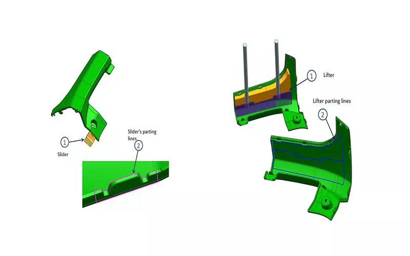
Injection molding sliders and lifters are both essential mechanical components used in molds to achieve the demolding of complex structures, but they differ in their applications and working principles.
Sliders are mainly used to release external undercuts, side holes, and other external features of plastic parts. They typically move laterally or at an angle within the mold and are suitable for handling complex geometries.
On the other hand, Lifters are primarily used to release internal undercuts, slender ribs, and complex internal structures. They perform a combined vertical and horizontal motion to lift the plastic parts from the mold core, making them ideal for parts with intricate internal features.
Sliders usually consist of guide pins, slider bodies, slide feet, and back wedges. The design of the slide foot and slide details, as well as the choice of slide material, significantly affect the slider’s wear resistance and service life.
Lifters include lifter rods, guide pins, return mechanisms, and wear plates, typically made from hardened steel to resist injection pressure and abrasion.
In terms of production efficiency, both sliders and lifters greatly enhance mold automation and demolding speed, reducing the need for secondary operations and improving product quality.
For large volume production, the proper design and coordination of sliders and lifters are especially important to ensure smooth demolding of the entire molding surface and large molding surfaces.
Additionally, the choice between sliders and lifters must consider the overall mold design, such as the fit when the mold closes, compatibility between slide material and gib material, and mold space constraints.
In summary, injection molding sliders and lifters each have their advantages. Selecting the appropriate demolding mechanism based on product structure and production requirements is key to ensuring the manufacturing of high-quality plastic parts.
Conclusion
In conclusion, the injection molding lifter, as an indispensable mechanical component in plastic injection molds, effectively solves the demolding challenges of complex internal undercuts through its unique combined vertical and horizontal motion.
It enhances the automation level of injection molding production and improves product quality, making it a key technology in modern injection mold design.
The design of injection molding lifters must consider not only their wear resistance and heat resistance but also ensure seamless coordination with the overall mold to achieve a smooth demolding process.
Proper lifter placement and precise motion control can effectively prevent product deformation and surface scratches, ensuring dimensional stability and aesthetic quality of the finished parts.
By optimizing material selection and motion mechanisms, manufacturers can significantly enhance production line automation, shorten production cycles, and reduce labor costs.
Looking ahead, injection molding lifter technology will continue to advance toward higher precision, greater durability, and intelligent features.
Integration with advanced sensors and control systems will enable real-time monitoring and automatic adjustments, further improving mold performance and product quality, thereby bringing greater innovation potential and competitive advantages to the plastic manufacturing industry.